
Digital Feature: Flare system design—The importance of periodic evaluation of existing facilities
Change is the only constant in most process facilities, particularly for managers of process safety. Over the past 15 yr, global refining capacity has grown by 13%, driven largely by the expansion of a relatively small number of highly efficient, profitable facilities. To maintain safe operations in this evolving landscape, process safety management (PSM) must adapt to ongoing changes within facilities. Keeping process safety information (PSI) up-to-date requires significant effort but offers substantial returns in terms of improved operational safety and reduced project costs. Revalidating the relief and flare system design is critical to ensure that PSI remains consistent with current operation.
Some facility changes—such as updates to piping and instrumentation diagrams (P&IDs) or equipment records—have an obvious impact on relief and flare systems design. Other changes that may seem subtle can have large impacts on relief and flare systems’ effectiveness in managing upsets or utility failures. Over the past 15 yr, in response to incidents and operational experience, there have been revisions in design practices, codes and standards related to the design of relief and flare systems. In addition to the challenge of keeping up with facility changes, economic and environmental pressures have driven increasing complexity in facility design, with significant implications for relief and flare systems.
This article emphasizes the critical importance of routinely revalidating relief and flare system designs, much like the periodic review of process hazard analyses (PHAs). A detailed case study is reviewed to illustrate the value of such revalidations.
Refining capacity and throughput growth. The more things change, the more they stay the same. In the U.S., refining capacity grew by 3% from 2008–2023, while the number of facilities decreased by about 16%, resulting in an average throughput increase of nearly 20% per facility.1 According to OPEC, global refining capacity increased by 13% in the same time frame, although the change in the number of operational refineries worldwide during this period was not specified, but is not expected to have changed significantly.2
From a design perspective, this translates to a 20% increase in facility throughput, on average, resulting in increased demands on the relief and flare systems. It also implies that equipment modifications, such as pump or control valve changes, were likely necessary to accommodate the increased throughput. Without review, such changes could introduce cascading effects, potentially leading to increased capacity requirements for both relief devices and disposal systems.
Additionally, facilities are becoming increasingly complex. The average Nelson Complexity Index (NCI) of refineries worldwide rose from < 8 in 2000 to nearly 10 in 2020.3 Similar trends are observed in chemical and other processing facilities, where increased complexity is driven by the need to enhance operating reliability, flexibility, cost efficiency and environmental compliance. However, as process complexity grows, the interdependence of systems increases, meaning failures or upsets in one area can have far-reaching consequences in other areas. This is especially critical for relief and flare systems, which serve as the final line of defense against overpressure which can result in catastrophic failures.
Beyond facility changes, it is often beneficial to have a fresh perspective in the review of a system. Assumptions made during the design phase or previous reviews may no longer hold or may not have been implemented during construction. The authors' extensive experience highlights the importance of revisiting past assumptions to ensure continued reliability and safety.
Finally, this article assumes that the facility has a relief and flare system design as part of the PSI. If a facility lacks such information, readers are advised this information is critical for the safe operation of a facility and feeds into many other safety and risk analyses (e.g., PHAs).
TOP FOUR REASONS TO PERFORM A RELIEF AND FLARE SYSTEMS REVALIDATION
Too many incidents have been linked to loss of containment due to undersized relief devices or disposal systems, many of which are documented on the U.S. Chemical Safety Board's (CSB’s) website. The following is a partial list of incidents caused by inadequate relief or flare system designs, based on CSB reports:
- Sonat Exploration, Pitkin, Louisiana (1998): A separator was isolated from its normal relief path during maintenance operations and subsequently failed when exposed to high pressure.
- bp, Texas City, Texas (2005): A tower overfilled, causing effluent to flow into an undersized condensable blowdown drum, which led to an uncontrolled release of hydrocarbons, resulting in a fire and explosion.
- D. Williamson, Louisville, Kentucky (2013): An additive processing tank overpressured and lost containment, as it was not protected by a dedicated relief device.
- DuPont, Laporte, Texas (2014): An inadequate relief design and disposal system caused operator fatalities due to a combination of asphyxia and acute inhalation exposure to methyl mercaptan.
These U.S.-based incidents underscore the critical importance of a robust relief system design basis. Outside the U.S., the UK’s Health and Safety Executive (HSE) documented notable incidents, including the 1987 bp Grangemouth explosions and the 1994 Texaco refinery fire in Pembrokeshire, both linked to deficiencies in flare system design.
#1. Facility changes. When a facility undergoes modifications, it is critical to review the relief and flare systems to ensure that these changes do not compromise the ability to provide overpressure protection. While most operational facilities execute different types of projects, these projects often result in effects on the relief and flare systems outside their immediate scope, which can go unaddressed. These projects include:
- Capacity increase projects: These projects are to increase the capacity of an existing facility or unit. Typically, a team of engineers review equipment within the project scope to ensure satisfactory performance at higher rates. However, in the authors’ experience, the impact of these changes on surrounding units and existing flare systems is often overlooked or assumed to be minimal.
Projects often approach flare system impacts by assuming that changes will only affect areas upstream of the tie-in point, disregarding the potential for increased flare loads from the modified unit to impact the entire flare system. This narrow perspective can lead to significant underestimation of the project’s broader implications on the relief and flare systems.
- New units (greenfield): These projects involve designing and constructing a new unit, train or plant that integrates with existing utility systems, including flare headers. While the relief and flare systems for the new additions are typically designed to meet requirements, the potential impacts on the existing relief and flare systems are often inadequately addressed—similar to capacity increase projects.
- Capacity creep: These small, in-house changes debottleneck individual pieces of equipment or parts of a unit. Subtle modifications, such as a control valve trim change, are often deemed insignificant and bypass relief system design reviews. Over time, these incremental changes accumulate and can create major issues for relief systems or low-pressure equipment.
- Optimization projects: These projects aim to reduce energy consumption, lower emissions or enhance feed flexibility. A common outcome is a significant increase in complexity of equipment, energy/heat and process interconnectivity. For example, the impact of heat integration projects on overpressure analysis can be so intricate that extensive papers have been published to guide designers in evaluating their effects on relief and flare systems.4
- Reliability projects: These projects aim to improve facility reliability, often by increasing equipment redundancies through the addition of critical spares or utility supplies, such as feeders or electrical buses. In other cases, reliability is enhanced by switching pump drivers from steam to electric or vice versa. However, such changes frequently alter the foundational basis underlying relief and flare systems analyses. For example, at one U.S.-based facility, the addition of a redundant electrical feeder, which achieved its objective to improve reliability also resulted in an electrical feeder failure that overloaded the flare system due to those same modifications.
The common issue across these projects is their narrow focus on immediate changes while failing to comprehensively evaluate the impacts on relief and flare systems. Over time, the cumulative effect of many projects can significantly deviate the relief systems design from its original state. This is especially true for optimization and reliability projects, where, in the authors’ experience, impacts on flare and disposal systems are often significantly underestimated. Regular reviews and updates to relief system designs are necessary to address these evolving challenges.
#2. Changes to the design and regulatory requirements. Regulations, codes and standards are written from experience. Over time, these design guidelines evolve to incorporate lessons learned from incidents and near-misses. While older designs are sometimes “grandfathered,” this is not always the case. Many regulatory compliance requirements, such as environmental modifications, are addressed during project changes; however, updates to design requirements often require a separate review. Even if a facility maintains flawless PSM execution, changes in design standards necessitate periodic reevaluation.
A prime example is American Petroleum Institute (API) Standard 521, the most widely recognized standard on relief and flare design, which has undergone significant updates between its 4th edition (1997) and its 7th edition (2020). Some of the key updates include5:
- Overfilling: This standard previously considered overfilling of distillation equipment and large vessels to largely be “not credible.” Incidents since the early 2000s have resulted in changes to this philosophy. Currently, this standard recommends far stricter guidelines for evaluating liquid overfilling scenarios.
- Operator intervention: Historically, little consideration was given to an operator’s ability to respond to a process upset. If the upset could be handled within 10 min, it was generally considered acceptable to rely on operator intervention instead of using a relief device. However, the 7th edition of API 521 now requires designers to critically evaluate the feasibility of operator intervention. This evaluation must go beyond simply ensuring adequate response time and consider additional factors, such as:
- Instrumentation to ensure operators are fully aware of the situation
- A reliable means of action to control the overpressure scenario
- The potential for cascading effects of the intervention on other equipment
- Training and procedures for effective response to the scenario
- The prioritization of this overpressure scenario during a larger-scale event
- Consideration of the consequences should the operator fail to act.
Only after thoroughly assessing these and other considerations can credit for operator intervention be taken in relief and flare system design.
- High-/low-pressure interfaces: Interfaces between high- and low-pressure systems, such as pipe specification breaks, have undergone significant updates. While the 4th edition of API 521 provided a brief warning about backflow risks from check valves, it offered limited guidance. Drawing from incident data, the latest standards now recommend a more rigorous analysis of both backflow and forward flow risks. These requirements particularly emphasize equipment such as level control valves, check valves, and pump or compressor stations, where such risks are most prevalent.
- Non-normal operations: The 4th edition of API 521 included only a passing reference to overpressure risks during non-normal operations, such as maintenance line-ups. Many incidents documented by the U.S. CSB occurred during non-normal operations (e.g., start-up and shutdown). As a result, the 7th edition of API 521 significantly expands requirements for analyzing overpressure risks during non-normal operations.
Additionally, regulatory trends have led to the incorporation of more units for environmental protection, further complicating design requirements. These project-driven changes highlight the importance of staying up-to-date with evolving standards to ensure compliance and operational safety.
#3. Relief device-focused records. In the early years of the PSM standard, relief systems documentation was commonly organized around relief devices, often stored in a “relief device” folder. While this approach may seem logical, it overlooks a critical reality: equipment, not relief devices, is the primary focus of overpressure protection. This organizational method leads to a significant issue: if a piece of equipment lacked overpressure protection in the original study, it is likely to remain overlooked in subsequent updates. Projects typically prioritize record updates as part of their scope, but with project managers striving to limit scope creep and adhere to deadlines, any missed equipment items will likely continue to be excluded from review.
A similar oversight occurs with utility failures, such as a power failure. If a system was not originally analyzed for utility failures, or if changes have since created new applicable overpressure scenarios, these effluent loads are often missed. Projects that focus solely on the existing design basis can fail to account for subtle process changes or new conditions that significantly impact overpressure requirements. Without a comprehensive evaluation of changes, designers may overlook critical criteria or fail to recognize the potential for significant loads to the flare or disposal system.
To address these gaps, a comprehensive relief and flare systems study is essential. Such a study ensures that all equipment in the facility is adequately protected against overpressure and that the disposal and collection systems are designed to handle concurrent effluent loads resulting from potential utility failures.
#4. As-built vs. as-designed verification. When considering the review of a facility's relief and flare systems design, it is critical to recognize that not all equipment specified during original design or subsequent projects was installed or remains operational. Over time, as projects accumulate, these discrepancies can multiply, increasing the gap between the PSI and the installed systems.
While it might seem rare for specified safety systems to be left uninstalled or deactivated, this occurrence is surprisingly common. In fact, verifying the presence and functionality of shutdown systems listed as safeguards is typically one of the first steps in any relief systems review.
A comprehensive relief and flare systems study addresses these gaps by ensuring that all required safeguards and protective instrumentation are properly identified, installed, and regularly tested.
Develop a design basis. A relief and flare systems design basis is essential for ensuring that overpressure protection and effluent handling systems can manage loads during equipment or utility failures, such as power outages. The authors have developed a document aligned with the American Occupational Safety and Health (OSH) Act, which serves as a widely adopted minimum standard for global operating companies, even for facilities outside the U.S.6
If a facility lacks a design basis, creating one is imperative to guarantee safe operation and compliance with corporate and regulatory standards. A comprehensive relief and flare systems study is not only a proactive safety tool but is also cost-effective. Identifying and addressing undersized systems during a study is far less expensive than experiencing a process upset that escalates into a loss of containment incident. Such incidents could otherwise be mitigated by appropriately sized relief devices that transform potential disasters into controlled releases.
Relief and flare system design basis revalidation. This section outlines the key steps and required information for revalidating a relief and flare system design. Before beginning the revalidation, a set of design and installation requirements for the relief and flare systems must be established. These requirements serve as the criteria to determine whether installations meet the company’s standards.
The case study presented in the next section is based on corporate standards that meet or exceed the requirements of Recognized and Generally Accepted Good Engineering Practices (RAGAGEP), which include guidelines published by API, the American Society of Mechanical Engineers (ASME), the Energy Institute and other industry organizations. Any deviations from these criteria must be documented and reviewed further. The revalidation process included the following major steps:
- Confirming current process safety information:
- Obtain a heat and material balance representative of current operation.
- Gather mechanical data for all equipment and piping, including size, elevation, maximum and minimum acceptable pressures and temperatures, inspection history, and insulation status.
- Collect performance and flow data for pumps, compressors and control valves.
- Confirm the size and routing of relief device inlet and outlet piping from the equipment to the flare tip.
- Obtain current cause-and-effect diagrams and probability of failure on demand (PFD) data for high-integrity pressure protection systems (HIPPS).
- Note: Unavailable PSI may need to be developed prior to the revalidation effort.
- Individual equipment system overpressure analysis:
- Perform scenario identification for all overpressure scenarios defined in the design and installation requirements and verify credit for safety systems (e.g., HIPPS, insulation).
- Estimate the relief requirements for all applicable overpressure scenarios, considering current equipment and operational conditions.
- Size the relief device(s) to ensure adequate capacity and verify installation (e.g., inlet/outlet pressure losses, pipe support, sloping, temperature limits).
- Global scenario and flare/disposal system analysis:
- Identify potential utility failures that could lead to system-wide or multiple-system overpressure events (e.g., power failure, bus or feeder failures, steam failure, cooling water failure, instrumentation failure or air failure, large-scale fires).
- Create a hydraulic model of the flare or disposal system to confirm that the piping size and material selection are adequate to safely handle all potential releases.
- Verify that network equipment (e.g., liquid knockout drums, seal drums, flare or incinerator) are properly sized to safely manage all potential relief loads.
- Dispersion modeling—whether to a standard vent or a flare/incinerator—to verify that resultant discharges do not exceed risk criteria for toxic or flammable emissions. This is also relevant for flare/incinerator systems, as flameout events can result in the uncontrolled release of non-combusted effluent.
The documentation in the following case study was performed using a software tool that enables the facility to update calculations easily as the facility undergoes upgrades (projects) or smaller changes [management of change (MOC)].
CASE STUDY: GAS OIL SEPARATION PLANT
As part of the Saudi Aramco’s Flare System Design Digitalization Initiative, and to ensure compliance with both industry and company standards, one of the major producing facilities was selected for a comprehensive relief and flare system revalidation. This gas oil separation plant (GOSP) was chosen due to its critical role in supplying oil to the Middle East North Africa (MENA) region and major Asian markets.
Although the facility is only 15 yr old, its relief and flare system documentation had become a fragmented collection of original design and project documentation limited to specification sheets. The facility’s safety team needed a complete and current design basis for the relief and flare systems to accurately evaluate the impact of changes (MOCs) and carry out comprehensive PHAs.
The GOSP in this study is a standard gas oil processing facility that separates incoming three-phase raw crude into gas, oil and water fractions. The oil fraction is stabilized before being either pumped to crude export pumps or stored onsite, if necessary. The associated gas is directed to nearby gas processing facilities, while the produced water is pumped back into the reservoir via dedicated pipelines and disposal headers.
FIG. 1. provides a simplified process flow diagram (PFD)/block flow diagram of a single process train.
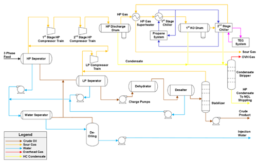
FIG. 1. A simplified flow diagram of the GOSP.
Each unit has its own relief system and flare headers, while the facility operates a high-pressure, low-pressure and common flare system (FIG. 2).
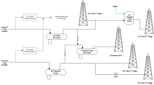
FIG. 2. A simplified flare diagram of the GOSP.
As part of its commitment to environmental sustainability, the company has implemented a state-of-the-art flare gas recovery system to minimize carbon emissions.
Relief device analysis. The relief device analysis revealed design gaps and deviations. Nearly all these deviations were attributed to safety equipment that was either not installed or installed but not identified or tested per the company’s requirements.
While validating the major findings, the revalidation team discovered that the original designers had specified HIPPS for overpressure protection. However, these HIPPS were not explicitly documented in the facility’s critical instrumentation lists, analyzed in past PHAs, or incorporated into preventive maintenance programs, operator training or written manuals. A key result of this study was to inform the site and operations team of the critical reliance on multiple HIPPS systems for the adequacy of the relief and flare systems.
FIG. 3. illustrates the prevalence of deviations identified during the relief and flare systems revalidation effort for the GOSP. These deviations are discussed in greater detail in the subsequent section.
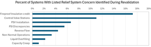
FIG. 3. Summary of major relief and flare deviations.
The revalidation team collaborated with the operations team to develop practical and feasible recommendations to address the identified concerns. By implementing these solutions efficiently, the facility improved safety and compliance with company standards while minimizing operational disruptions.
A detailed description of major findings. The following is a more detailed description of the items listed in FIG. 3. While these are not the only issues identified in the study, they represent the most pressing concerns requiring attention:
- Fireproof insulation credit: The revalidation effort determined that approximately one in six systems was potentially undersized if exposed to an external fire, when evaluated under current operating conditions using current calculation methods. Before notifying management that these systems might not meet company standards, field technicians conducted an onsite review to confirm the presence of fireproof insulation.
Although all equipment was insulated, the insulation failed to meet the fire resistance criteria specified for reducing relief loads for fire exposure.
Since the original overpressure analysis, conducted 15 yr ago, was unavailable, the revalidation team identified two possible explanations:
- The original designers may have incorrectly assumed that process insulation was fireproof
- Fireproof insulation was specified but never installed.
When these systems were re-evaluated under the assumption of properly installed fireproof insulation, each system was found to be adequately protected from overpressure.
- Control valve stations: One in nine systems contained control valve stations that, when analyzed against company standards, had the potential to overpressure downstream equipment and did not meet relief system requirements. Due to the absence of the original design basis, it remains unclear whether these control systems were built as originally specified or modified after the relief system designs were completed. Regardless, these systems lacked adequate overpressure protection, highlighting the need for further evaluation and potential corrective actions.
- Reverse flow: Approximately 5% of the systems—primarily feed or compressor surge drums—were found to be at risk of overpressure due to backflow following a pump or compressor shutdown. This scenario has been a key focus in industry safety discussions since the facility was constructed, due to lessons learned from high-profile incidents shared in industry forums. The P&IDs indicated the presence of shutdown systems intended to mitigate backflow effects, but without a documented probability of failure on demand (PFOD), these systems could not be assumed to be sufficiently reliable under company standards to prevent overpressure.
- Non-normal operations: A few systems were identified as susceptible to overpressure if utility valves were misaligned or inadvertently opened. Non-normal operation scenarios appear to have been overlooked in the original facility design. However, since the 2008 Goodyear incident and the 2013 Williams incident,7,8 the risk of overpressure from abnormal operating line-ups has received more industry attention.
- Liquid overfilling: There were a couple of systems that did not have sufficient relief capacity to prevent overpressure in the event of overfilling. Similar to reverse flow risks, the P&IDs indicated that HIPPS may have been intended to mitigate the overfilling scenarios. While the revalidation team recognized the presence of HIPPS systems designed to prevent overfilling, without a documented PFOD, these systems could not be assumed to be sufficiently reliable under company standards to prevent overpressure.
- Capacity creep: A system was found to be undersized in the event of a normal process flow stoppage. The revalidation team assumed that the system had been installed with adequate overpressure protection. However, incremental modifications and small process changes over time resulted in the existing relief system no longer being adequately sized according to the company’s relief system design philosophy.
In addition to these findings, the revalidation effort identified relief devices that were not installed per company standards and exhibited excessive inlet or outlet pressure losses. Furthermore, the revalidation team discovered discrepancies in PSI for approximately 5% of systems, all of which were documented and resolved.
With the mitigation of these individual relief scenarios and the verification and necessary upgrades of HIPPS to prevent overpressure, the flare and disposal equipment was deemed adequately sized. However, if the HIPPSs are later determined to be inadequate, significant modifications to the flare and flare network equipment may be required.
Takeaway. A comprehensive relief and flare system design update is essential to ensure that facilities maintain adequate overpressure protection and safe effluent disposal as they evolve.
For many facilities, the existence of relief and flare system documentation leads PHA teams and other risk assessors to assume that the system is currently properly designed. However, in the case of the GOSP examined in this study, significant gaps were identified in several overpressure scenarios. The flare and relief system relied on HIPPS that were not classified as critical instrumentation, lacked a documented PFOD and were not maintained as substitutes for relief devices in providing overpressure protection.
Additionally, multiple equipment were found to be at risk of significant overpressure in the event of a fire, and there was a potential for overpressure due to non-normal operations that had not been previously addressed.
Relief and flare system revalidation efforts help facilities identify difficult-to-detect risks—the proverbial needle in the haystack—through structured engineering studies, allowing concerns to be mitigated proactively rather than discovered through operational failures.
DISCLAIMER
The information contained in this article represents the current view of the authors at the time of publication. Process safety management is complex, and this document cannot embody all possible scenarios or solutions related to compliance.
This article contains examples for illustration and is for informational purposes only. Saudi Aramco and Smith & Burgess make no warranties, express or implied, in this work.
LITERATURE CITED
1 U.S. Energy Information Administration (EIA), Refinery capacity data, January 7, 2025, online: https://www.eia.gov/dnav/pet/hist/LeafHandler.ashx?n=PET&s=8_NA_8O0_NUS_C&f=A
2 Organization of the Petroleum Exporting Countries (OPEC), Annual Statistical Bulletin 2024, OPEC, January 7, 2025, online: https://publications.opec.org/asb/Download
3 Tobin, D., “Captive markets and climate change: revisiting Edith Penrose’s analysis of the international oil firms in the era of climate change,” International Review of Applied Economics, August 14, 2024.
4 White, J. P., “Heat integration and relief systems design, 9th Global Congress on Process Safety, American Institute of Chemical Engineers (AIChE), San Antonio, Texas, 2013.
5 American Petroleum Institute (API), API Standard 521: Pressure-relieving and Depressuring Systems, Washington D. C., API, 2020.
6 Smith, D., Minimal Requirements for Relief Systems Documentation, Smith & Burgess, January 8, 2023, online: https://www.smithburgess.com/resources
7 U.S. Chemical Safety and Hazard Investigation Board, “Goodyear heat exchanger rupture,” U.S. CSB, Washington D. C., January 27, 2011, online: https://www.csb.gov/goodyear-heat-exchanger-rupture/
8 U.S. Chemical Safety and Hazard Investigation Board, “Williams Olefins plant explosion and fire,” U.S. CSB, Washington D. C., October 19, 2016, online: https://www.csb.gov/williams-olefins-plant-explosion-and-fire-/
The Authors

Hasan Amin is a Senior Process Engineer with the process and control systems department at Saudi Aramco in Dhahran, Saudi Arabia. He has nearly 22 yr of experience in the process and operations of oil and gas and petrochemical industries. Prior to joining Saudi Aramco, Mr. Amin worked with CH2M Hill (formerly VECO Canada), Worley Parsons Canada, and others in the process engineering department. Throughout his career, Mr. Amin has worked in various project lifecycle activities, including proposals, conceptual design, front-end engineering, detailed engineering, construction support, commissioning, operations and maintenance. He earned a BSc degree in chemical engineering and an MSc in total quality management (TQM) from the University of Punjab, Pakistan, as well as an MEng degree in chemical and petroleum engineering from the University of Calgary, Canada. He is a registered professional engineer in Alberta, Canada.

Dustin Smith earned a BS degree in chemical engineering from Texas A&M University and is a licensed professional engineer. He co-founded Smith & Burgess in 2007 and serves as Co-Owner and CEO. With more than 25 yr of experience, he specializes in relief systems design, PSM compliance audits, flare system optimization and incident investigations. Smith has contributed to API 520/521 committees and led projects that improved safety, compliance and operational efficiency for clients globally.

Yousef Aloufi is a Process Engineer at Saudi Aramco, working as a subject matter expert in flare and relief systems. Aloufi has led key initiatives to reduce the environmental impact of industrial processes by developing innovative flare monitoring and minimization plans, leading to major contribution to corporate decarbonization strategy. He has also co-invented five patents related to emissions monitoring in flare systems. Aloufi earned BS degree in chemical engineering from the University of New Brunswick, and a Masters degree in chemical engineering and an MBA both from Cornell University.

Shahin Zafari earned an MS degree in chemical engineering from Lamar University and is a project manager at Smith & Burgess. He has more than 10 yr of experience managing relief and flare systems design projects worldwide across the oil, gas and petrochemical industries. Zafari has extensive knowledge of PSM and excels in relief and flare systems design, revalidation, flare optimization, concern resolution and compliance with industry standards and codes

Omar Thiam earned a BS degree in chemical engineering from Prairie View A&M University, and is a Technical Manager at Smith & Burgess. He has more than 10 yr of experience in PSM. He specializes in relief and flare systems design, revalidation, concern resolution and documentation within the oil, gas and petrochemical industries. Thiam has taught relief system design courses globally and is a detail-oriented problem solver focused on client safety and compliance, with expertise in flare optimization, heat and material balance generation, dispersion analysis, and engineering software systems.


Comments