
Digital Feature: The critical interdependency of relief valve analysis and flare system considerations during HAZOP
Hazard and operability (HAZOP) studies are a systematic and structured methodology used to identify potential hazards and operability issues in industrial processes. HAZOP is conducted in the workshop style, where interdisciplinary stakeholders come together and identify the gaps and design safeguards to bridge the gaps in the plant design. The technique typically relies on guide words (e.g., no, more, less, part of) to systematically evaluate deviations from design intent and their potential consequences. One of the key safeguards often considered in HAZOP studies is pressure relief valves (PRVs) and flare systems to mitigate overpressure scenarios.
However, the effectiveness of PRVs as safeguards is contingent upon a thorough understanding of their design, operation and integration with the broader pressure relief and flare systems. A systematic pressure relief analysis is essential to ensure that relief devices are appropriately sized, located and designed to handle worst-case scenarios. However, best practice dictates identifying all relevant scenarios for each system or piece of equipment and justifying the credibility of each scenario with adequate rationale. All scenarios, whether credible or not, should be clearly identified during the HAZOP study.
A comprehensive flare system assessment—a crucial part of this process—involves several key aspects. First, it requires meticulously identifying all potential scenarios that could lead to overpressure, including process upsets, external events and maintenance activities. For each scenario, credibility and potential consequences must be determined. Second, relief device sizing and location are crucial, involving calculating relief loads, selecting appropriate devices and ensuring proper placement. Third, the flare system itself must be designed to handle the maximum anticipated relief load, high and low temperatures with the appropriate selection of materials, adequate flare header sizing to avoid high back pressure, mechanical backpressure, flare stack design (height and diameter for proper dispersion and radiation), the knockout (KO) drum for liquid separation, removal of condensate formed after the KO drum to avoid liquid carryover to stack and a reliable ignition system. Fourth, flare system operability and maintenance are essential, including relief device testing, regular inspections and established maintenance procedures. Finally, environmental considerations—such as emissions, noise, and potential smoke and light—must be addressed.
Based on the relief valve and flare system assessment, credit may be taken for a relief valve as a reliable barrier, but only after careful consideration of its reliability, independence and applicability to the specific scenario. This analysis must be equipment-based, meaning it should consider the specific fluid composition and operating conditions of each piece of equipment in the system.
Example. Due to high back pressure, a pilot valve was recommended; however, adequate attention was not paid to the fluid composition, which was not clean. Credit for this valve was taken in the HAZOP for vapor relief scenarios without looking at the service. As a result, overpressure protection might be compromised, as the pilot may become blocked, and the functionality of the pilot-operated valve will be compromised.
To avoid such oversighting, a well-developed HAZOP study is required—the study should not remain a "shelf document" but should serve as a practical operating guideline for plant operators. By translating HAZOP findings into actionable procedures, operators can better understand the risks associated with deviations and the safeguards in place to mitigate them. This approach ensures that the HAZOP study becomes an integral part of daily operations, enhancing both safety and operational efficiency.
INTERDEPDNCIES OF HAZOP AND PRESSURE RELIEF ANALYSIS
Pressure relief analysis is a critical component of process safety that ensures systems are protected against overpressure scenarios. It involves evaluating the design, sizing and placement of relief devices, as well as the capacity and integrity of the downstream flare system.
The interdependency between HAZOP and pressure relief analysis arises because:
- HAZOP identifies scenarios where overpressure may occur (e.g., blocked outlet, runaway reaction, external fire, total power failure).
- Pressure relief analysis ensures that the relief valves and flare systems can handle the identified scenarios safely and can be trusted as a last line of defense.
Scenario identification and credibility. A key aspect of pressure relief analysis studies is the identification of credible and non-credible scenarios. This requires a systematic approach to:
- Identify all relevant scenarios: Based on the specific system or equipment, scenarios such as blocked outlets, external fires, runaway reactions, total power failure and thermal expansion must be considered.
- Justify scenario credibility:Each scenario should be supported by detailed rationale, engineering calculations and process knowledge. Scenarios must have all sources connected to the equipment and a comparison of each source’s maximum pressure with equipment design pressure.
- Link scenarios to HAZOP causes:The identified scenarios should be directly linked to the causes identified in the HAZOP study. For instance, a runaway reaction scenario should be tied to causes such as loss of cooling or catalyst overcharging, ensuring a comprehensive understanding of the risks and safeguards.
Relief device sizing and selection. Once scenarios are identified, the next step is to ensure that the relief devices are appropriately sized and selected to handle the worst-case scenarios. This involves:
- Sizing relief valves:Using methodologies outlined in standards such as API 520 and API 521, relief valves must be sized to handle the maximum flowrates and pressures generated by the identified scenarios. This should be applicable not only to pressurized vessels but also to the low pressure tanks as per API 2000.
- Selection of relief valves:The type of relief valve (e.g., spring-loaded, pilot-operated) should be chosen based on the specific application, fluid properties and operating conditions. For example, pilot-operated valves may be preferred for high-capacity applications, while spring-loaded valves are suitable for smaller systems.
Identification of blowdown or depressurization valves. In some scenarios, relief valves alone may not be sufficient to mitigate risks. Blowdown or depressurization valves may be required to:
- Reduce system pressure:In cases of fire or equipment failure, blowdown valves can rapidly depressurize the system to prevent catastrophic failure.
- Calculate depressurization rate and temperature:The rate of depressurization and the resulting temperature drop must be calculated to ensure that materials remain within their design limits. For example, rapid depressurization can cause low-temperature embrittlement in carbon steel equipment.
Flare system assessment. The flare system must be designed to handle the relieved fluids safely and effectively. This involves assessing:
- High backpressure: Excessive backpressure can reduce the capacity of relief valves and cause operational issues. The flare system must be designed to minimize backpressure while accommodating the maximum relief load. Backpressure design limit and allowable backpressure limits on PRVs should be compared with the calculated backpressure.
- Mechanical backpressure issues: High backpressure can cause bellows valves to rupture, potentially leading to safety and operational issues. These limits should be obtained from the relief valve manufacturer or from API 526.
- Low-temperature and high-temperature concerns:
- Low-temperature concerns: Cryogenic fluids can cause embrittlement of materials, leading to potential failures in the flare system. Materials must be selected to withstand the lowest expected temperatures.
- High-temperature concerns: High-temperature releases can degrade materials and cause thermal expansion issues in piping and equipment. The flare system must be designed to handle the highest expected temperatures without failure.
- Material selection: The flare system must be constructed from materials resistant to corrosion, erosion and other degradation mechanisms caused by the relieved fluids. For example, stainless steel may be required for corrosive fluids, while carbon steel may suffice for non-corrosive applications.
- Large liquid releases: Large liquid releases to the flare system require careful evaluation to ensure safe operation. The flare header must be adequately supported to handle the additional weight and hydraulic forces from liquid flow. A properly sized KO drum is essential to separate liquids from the vapor stream, preventing hazardous fireballs or pool fires caused by liquid carryover at the flare tip.
Maintenance and operational issues. Several maintenance and operational issues must be considered during pressure relief analysis, including:
- Slug flow and two-phase flow: These can cause significant mechanical stress on the flare system, leading to vibrations, fatigue and potential failures. Proper design and operational controls are necessary to mitigate these effects.
- Suspended solids in relief fluid: Solids can clog relief valves or erode piping, reducing the system's effectiveness. Filters or separators may be required to remove solids from the relief stream.
Examples of interdependencies include the following:
- Thermal relief valves were deemed adequate during the pressure relief analysis inspection. Credit for these valves was taken in other HAZOP scenarios without considering the valve size or the type of fluid they would discharge. In some cases, thermal valves released liquid-containing suspended solid particles, which can clog the outlet pipe or reduce the flow line diameter, resulting in maintenance issue.
- A pressure relief and flare analysis address vapor release, liquid release and two-phase scenarios without considering any safeguards. However, HAZOP should identify potential two-phase scenarios and determine adequate safeguards to prevent two-phase releases to the flare system, thereby avoiding mechanical stress and potential system failure.
CONSEQUENCES OF TAKING CREDIT WITHOUT COMPLETE ANALYSIS
Taking credit for relief valves as safeguards without a thorough understanding of their design and integration with the flare system can lead to severe consequences, including:
- Inadequate relief capacity, low temperature and pressure drops. If the PRV is undersized, it may fail to relieve pressure effectively, leading to equipment failure or catastrophic incidents. Similarly, high pressure drops at the inlet and outlet of pipe of a relief valve could damage the valve, low temperature at the outlet of the valve and incorrect material of construction will lead to embrittlement and loss of containment.
- Flare system overload: Without analyzing the flare system's capacity, the release of large volumes of fluids can overwhelm the KO drum, piping or flare stack, resulting in system failure or environmental releases. Care should be taken whenever a new system is connected to the existing flare system—a new system may introduce new concerns, and the existing flare may not be originally designed for those concerns. Therefore, it is not recommended to take credit for the existing flare system based on a worst-case scenario determined from the new system alone. A wholistic review of the existing flare system, including the new system, should be conducted before considering the existing system as a reliable safeguard.
- Unmitigated hazards: Scenarios such as toxic releases, fires or explosions may occur if the relief system cannot handle the identified deviations.
FINANCIAL AND COMPLIANCE LOSSES
The consequences of inadequate pressure relief and flare system analysis extend beyond immediate safety concerns. They can result in:
- Financial losses: Downtime, equipment damage and environmental cleanup costs can amount to millions of dollars.
- Compliance losses: Regulatory fines and penalties can be substantial, and non-compliance can lead to increased scrutiny and stricter enforcement.
- Long-term impact: Repeated incidents can damage a company's reputation, leading to loss of business and difficulty in obtaining permits for future projects.
Additionally, HAZOP reports can be used in legal cases to demonstrate due diligence or negligence in process safety management, or it can be used in incident investigations. A well-documented HAZOP study can serve as evidence of a company's commitment to safety, while gaps in the study can be used against the company in litigation.
CASE STUDY: ETHYLENE SPHERE RELIEVE VALVE INCIDENT
The following case was selected to demonstrate the importance of the interdependencies between pressure relief analysis and HAZOP. It highlights why it is crucial to thoroughly review the credits of the pressure relief and flare system as safeguards during HAZOP.
Process description. The ethylene storage system consists of a sphere operating at a pressure of 20.2 barg (296 psi) and a temperature of –28.7°C. At the bottom of the sphere, there is a pump that transfers ethylene to the process. The discharge line of the pump is equipped with a relief valve that discharges to a flare system. The flare system includes a KO drum and a stack to burn the vapor.
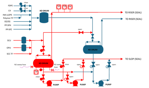
FIG. 1. Process flow schematic.
The issue. During a HAZOP study, credit was given to a relief valve without fully understanding its impact. The relief valve was discharging fluid at a low temperature, and the material of construction for the outlet pipe was not suitable for such low temperatures. This oversight led to a significant safety concern.
HAZOP report reviewer findings:
- Interim solutions: All analysis and mitigation measures were considered interim solutions. The full segregation of ethylene release should be considered as a permanent approach.
- Operating conditions: The ethylene sphere could operate at 20.2 barg (296 psi). There was no dedicated emergency depressurization valve, which is required for equipment operating at 250 psi or higher to prevent boiling liquid expanding vapor explosion (BLEVE) as per API 521, Para 4.6.4.
- Overfilling mitigation: Liquid overfilling of the sphere was mitigated with an instrumented system. A follow-up study is required to check the safety instrumented function (SIF) needed to mitigate the consequences of an overfilling scenario.
- SWIFT Analysis: The SWIFT analysis deemed asset damage as the worst consequence without considering environmental and safety consequences.
Ethylene sphere vapor:
- The risk was reduced through a process simulatora. The analysis referred to –20°C at the flare KO drum, but other low-temperature carbon steel locations upstream of the flare KO drum should be checked to ensure the minimum design metal temperature is not breached.
- The PRVs were not designed for a loss of cooling case on the sphere.
- The relief valve sizing basis showed overfilling was sized using a single-phase method. Since ethylene at saturated conditions would relieve as a two-phase flow, a more appropriate methodology from API should have been used.
Manual operation:
- Several scenarios could contribute to ethylene release to the flare header. The risk was mitigated through an equipment isolation sheet for control. It is advisable to clearly define and document the operator's actions in administrative controls to ensure clarity and effectiveness.
Pumps/rotating equipment:
- The study did not include a detailed analysis for pump de-staging. It is recommended to include the de-stage condition curve with the new required condition to support the study analysis.
- The maximum shutoff pressure will not be seen by the system downstream of the pump or the relief system. It is important to explain the reason for pump de-staging in this case.
- The possibility of leakage through a vent or drain is high if there is no proper design consideration/procedure for line isolation (e.g., blind double isolation). This requirement should be evaluated during the early stages of the project.
- From a rotating equipment point of view, there is no requirement in API standards requesting double isolation or blind since this is considered within the contractor's scope as defined necessary during design (HAZOP study).
Incident analysis. The primary reason for the incident was the introduction of low-temperature ethylene to the KO drum. Improper assumptions during the design phase resulted in operating the drum at a lower temperature (–100°C vs. –40°C). De-staging the pump would not improve this situation as the root cause was the incorrect design assumption.
Case study takeaway. This incident highlighted the importance of thorough analysis during HAZOP studies and the need for appropriate material selection for low-temperature applications. Interim solutions should be replaced with permanent measures to ensure safety. It is crucial to involve pressure relief and flare system experts during HAZOP studies to verify the design assumptions, review the PRV design and ensure that all safety measures are adequately addressed.
RECOMMENDATIONS
To avoid such gaps, the following recommendations are proposed:
- Integrate pressure relief analysis with HAZOP: Ensure that pressure relief analysis is conducted in parallel with HAZOP studies to validate the effectiveness of relief valves as safeguards.
- Conduct flare system analysis: Evaluate the capacity and integrity of the flare system (e.g., piping, KO drum, flare stack) to handle the scenarios identified in the HAZOP study.
- Verify PRV design and sizing: Confirm that relief valves are properly sized, located and designed to handle all cases, including the worst-case scenario identified in the relief assessment and HAZOP study.
- Use quantitative risk assessment (QRA): Incorporate QRA techniques to quantify the risks associated with relief valve and flare system failures to demonstrate the associated risks and determine the priority of mitigation to address the identified concerns.
- Train HAZOP teams: Provide training to HAZOP team members on the interdependencies between HAZOP, pressure relief analysis and flare system design. The best practice is to include the independent subject matter expert in the HAZOP session to carefully review the credits of pressure relief valve and flare system during HAZOP workshop.
- Document assumptions and limitations: Clearly document any assumptions or limitations related to relief valves and flare systems in the HAZOP report for more transparency and to avoid unintentional wrong credits.
- Periodic review and audits: Conduct periodic reviews and audits of HAZOP studies and pressure relief systems to ensure compliance with local regulation and company policy and to achieve the effectiveness of these two important studies.
DISCLAIMER
The information contained in this article represents the current view of the authors at the time of publication. Process safety management is complex, and this document cannot embody all possible scenarios or solutions related to compliance. This document is for informational purposes only. ERM and Saudi Aramco makes no warranties, express or implied, in this paper.
NOTE
a Aspen HYSIS
REFERENCES
- International Electrochemical Commission, IEC 61882:2016 – Part 3 Hazard and Operability Studies (HAZOP Studies) – Application Guide
- Center for Chemical Process Safety, Guidelines for Hazard Evaluation Procedures, 3rd Edition, Wiley, 2008
- American Petroleum Institute, API Standard 521, Pressure-relieving and Depressuring Systems, 7th Edition, 2020
- American Petroleum Institute, API Standard 520, Sizing, Selection and Installation of Pressure-relieving Devices Part I – Sizing and Selection, 10th Edition, 2020
- Boost the Value of Your HAZOPs with a Relief Systems Expert by Dr. Nancy Faulk and Praveen Dhote Siemens energy 2022, presented at Mary Kay O’Connor Process Safety Center 25th MKOPSC International Process Safety Symposium. College Station, TX
The Authors

Ahmer Irshad is a seasoned engineer with more than 25 yr of comprehensive experience in the oil, gas and petrochemical industries. He currently serves as an Engineer at Saudi Aramco. His extensive expertise ranges from hands-on project execution in both upstream and downstream operations to specialized technical skills such as simulating plant heat and material balances and calculating detailed piping pressure drop profiles for fluids. Irshad has a proven track record in managing complex process safety management projects in line with OSHA §1910.119 standards, and his leadership has consistently driven profitability and timely project deliverables for major domestic and international clients. Previously, he excelled as a Chief Engineer at Siemens Energy Oil and Gas Consulting in Houston, Texas (U.S.), and he is a respected speaker on process safety and SEMS topics at prominent industry conferences and academic lectures.

Husam A. Althaaly is a Chemical Engineer specializing in flare and relief systems at Saudi Aramco. He has 6 yr of experience as a dedicated process engineer specifically in hydrogen and isomerization operations. He has contributed to significant initiatives including the Ras Tanura Refinery Clean Fuels Mega-Project and has experience as an operations and project engineer. Althaaly actively engages in professional events, such as being an organizing committee member in the recent Middle East Process Engineering Conference (MEPEC 2024), reflecting his commitment towards the process engineering community.

Praveen Dhote is a Chemical Engineer and Consulting Director of Technical Safety at Environmental Resource Management (ERM) in Abu Dhabi, UAE. He has 24 yr of experience, specializing in process safety management studies, and his extensive experience includes working on projects in Asia, central Africa, the Middle East and the U.S. Dhote has led various process safety studies for more than 18 yr, such as quantitative risk assessment, process hazard analysis, pressure relief analysis and flare header analysis, among others for oil and gas, petrochemical and chemical projects at various locations. He is also a certified functional safety professional and hydrogen safety engineer. He graduated in 2001 from the Laxminarayan Institute of Technology at Nagpur University in India.


Comments