
Digital Exclusive: How companders can support industrial decarbonization
The climate emergency has persuaded almost all the world's leading chemical and petrochemical companies to commit to lower carbon intensity in their operations. Most have developed dedicated decarbonization roadmaps to achieve this goal. As a result, some key technologies and strategies have gained prominence, such as using green or blue hydrogen (H2); carbon capture, utilization and storage (CCUS); the electrification of operations; the use of renewable energy; and improving energy efficiency.
This article focuses on energy recovery, a crucial method of increasing the efficiency of an operation and thus reducing overall energy consumption. In doing this, it highlights the role a piece of technology plays in increasing efficiencies in both petrochemical/chemical and LNG industries: the compander, which—as the name indicates—integrates the function of a compressor and expander on the same unit.
After introducing the compander, this article presents three scenarios that illuminate this technology’s central role in increasing operational efficiency and recovering waste energy.
The compander: A compact single-skid unit. Lowering energy consumption, reducing carbon dioxide (CO2) emissions and using available plant space more effectively are not only core energy transition goals, but they are also key compander characteristics. Designed with both compressor and expander stages on a single gearbox (known as an integrally geared unit), the compander features one oil system, one control system and one seal-gas panel. A major benefit is that there is no need to have these components twice. Combining compressor-expander functions on one compact single-skid unit comes with a faster installation time, a smaller footprint and lower capital expenditures (CAPEX).
Moreover, combining sets of two technologies on one gearbox means the compander can use the energy recovered on the turboexpander side to directly power the compressor’s energy cycle. Typical applications of radial turboexpanders are H2 and natural gas liquefaction, and cryogenic hydrocarbon separation in ethylene or propylene production or air separation processes. The following presents three scenarios in which the compander has been employed to save energy, recover waste energy and save space:
- LNG liquefaction
- Converting hydrogen peroxide to propylene oxide (HPPO)
- Removing nitrous oxide from an exhaust gas stream.
1. LNG liquefaction cycle. In small-scale LNG (SSLNG) plants, the refrigeration compressor is the main power consumer. There are different types of refrigeration technologies applied in the SSLNG market. Larger SSLNG plants run steady and focus on best efficiency with minimal starts and stops, meaning a mixed refrigerant cycle is typically preferred. In contrast, smaller plants sometimes operate at full-capacity production, but will also have to operate in turndown mode, or even intermittently, with more frequent start/stop intervals, as well as operating in a suboptimum range. The reverse Brayton cycle is used in applications requiring compactness, operational flexibility and rapid start-up/shutdown.
Compander stages. Depending on customer requirements, the compander can have a different combination of stages. Compressor sections vary in most cases between three and four, and sometimes five, stages. Older plants often have one or two expander stages installed in series, meaning both expander stages physically use the same amount of 100% compressed flow, which is passed through both stages one after the other.
Warm and cold expander stages are typically installed next to each other, both at the non-drive end side of the gear box where the cold box is positioned (allowing for the shortest pipe connection to the cold box). The connection of the pinions via the gearing allows higher (or also lower) compressor loads than would be possible for a single-skid arrangement. The process can be optimized for either CAPEX, meaning fewer stages with higher loads, or operating expenditure (OPEX), meaning more stages and more intercooling for best efficiency.
CAPEX. The CAPEX for a new greenfield SSLNG plant varies depending on various factors such as plant size, chosen refrigeration technology, selected equipment type and the amount of standardization required. Combining the compression and expansion part of the process on one gearbox further reduces both the footprint and investment costs.
The rotating equipment for compression and expansion of the refrigerant typically represents a major portion of the total plant cost. With all rotating equipment combined on one gearbox, a compander’s gearset and oil systems are slightly larger compared to single-skid solutions, but there is no need for an entirely separate warm and cold expanders, and a high amount of pre-fabrication and pre-assembly can be carried out in the workshop prior to installation. Moreover, one larger skid instead of two separate skids allows for a faster erection time, with typical installation savings of about 25% for two skids vs. one single skid that is a little larger.
OPEX. Combining the warm- and cold-end stages on one common gearbox with the compressor improves efficiency and reduces OPEX. Speed and power can be different for each single impeller or impeller pair, allowing further loading of the compressor stage and more head. The compressor stage can take the entire expander's generated power, and the main driver via the gearing supplies the additional power for optimized stage design. By using this recovered waste energy, it allows for better compressor stage efficiencies, and consequently better overall coefficient of performance figures due to a more equal load distribution between all compressor stages. Depending on the process design, internal comparisons show figures of about 2% gain in efficiency for a compander design.
It is important to note that maintenance intervals for the compander are identical to that of single-equipment systems. The units adhere to API 617 requirements for operation of up to 5 yrs without major overhaul, while the required running time between two inspections can be customized for each job and combined with the overall plant service intervals.
2. Companders in HPPO. Companders installed in a HPPO process within an air-nitrogen compression-expansion service at a plant in Belgium highlight the technology’s value in energy recovery.
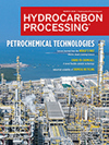
Process. Atmospheric air is compressed in four intercooled turbocompressor stages to around 7 bar and delivered to an oxidizer column where it reacts with an organic solution to a pre-product of hydrogen peroxide. A pressurized nitrogen stream remains, which is routed to expander stages to recover energy. Before entering the expander, the temperature of the nitrogen stream is increased by the pre-heater, and the enthalpy from the hot discharge air of the compressor is transferred to the nitrogen stream. This energy would be lost in the post-cooler (cooling water) if not transferred to the nitrogen stream. A large portion of the enthalpy of the hot nitrogen is converted into shaft power by the expander before the stream is delivered to a solvent recovery unit.

FIG. 1. Compander in the HPPO process.
The compander design. The core compander unit in the HPPO process is mounted on a combined gearbox/oil-tank unit, with interstage coolers fixed separately on the foundation. The gearbox fulfils the function of power distribution in a multistage integrally geared machine, and the gearbox is driven predominantly by an electric motor which acts directly on the driving gear (the low-speed bull gear). The expander stages provide additional high-speed driving power, turning the high-speed pinion shafts into a drive gear. Due to its huge amount, the incoming nitrogen is supplied via a tee piping to the expander stages, so that the expanders stages are running in parallel at identical inlet and outlet conditions. The impellers are arranged back-to-back on one common high-speed pinion shaft.
The result is that more than one third of the compressor coupling power is provided by the expanders. In recovering this waste energy, the amount of energy saved means the payback period for the compander investment was under 2 yrs.
3. Companders in nitrous oxide removal. Companders can be employed with low gas flows, such as in the removal process of nitrous oxide from exhaust gas streams. Nitrous oxide is a highly potent, tightly regulated greenhouse gas and is often an undesired byproduct during industrial processes. For lower flows such as in this example, Atlas Copco’s single-lift compander design is often utilized, meaning the motor, oil system and seal-gas system are integrated onto a single lift skid.
Process. The compressor compresses gas from an exhaust pipe from 7.5 bar to 25.5 bar. The pressurized gas is delivered to a washing column, where the nitrous oxide is removed. After removal, the pressure needs to be reduced back to 7.5 bar and fed back to the exhaust system. Before entering the washing column, the compressor discharge gas stream passes a heat exchanger, where it is cooled using the processed gas stream and leaves the washing column. The enthalpy is transferred to the gas stream leaving the column, which is routed to the expander, where the energy is recovered and the pressure reduced back to 7.5 bar.
The compander design. The expander stage runs on its own pinion with a single impeller driving the bull gear. The motor balances the power difference of the expander and the two-stage compressor with a back-to-back arrangement on a common pinion. Due to the formation of nitric acid in the condensate, suitable chromium nickel alloy materials had to be selected for the casing, shaft and impeller
The result of the integration means that around 47% of the compressor power is provided by the expander energy, which is recovered from the stream. Additionally, the compressor consumes 1.473 kW and the expander delivers 697 kW.
Takeaways. Compander technology is a long-term investment with immediate benefits. From plant footprint to installation and operational costs, companders have proven advantages compared to compressors and turboexpanders supplied as separate skids.
Capital expenses for a new plant can be lowered with one skid on a single frame and one oil system and one control system rather than separate skids. Operational efficiency can be increased because of the increased flexibility in optimizing aerodynamics of the compressor stages. As this article showed, the compander’s employment in various processes highlights the technology’s value in energy recovery. Higher overall efficiencies help push sustainability, decarbonization aims and drive forward the energy transition.

Comments